Audio Jack Diagram : Understanding Audio Jack Switches and Schematics | CUI Inc - 2.5 mm jack wiring diagram.. A wiring diagram usually gives opinion about the relative slope and bargain of devices and terminals upon the devices, to support in building or servicing the device. Understanding the wide variety of configurations available, including conductor count and switch options, enables designers to make the most of this familiar, compact, and reliable interconnect solution. In this article, we're only discussing unbalanced or 'general' use audio jacks. Wiring diagram for 3 5mm headphone jack the front panel also hosts a 35 mm headphone jack powered by the built of cutting and stripping speaker wire. It is also known by other names like phone jack, audio jack, aux input, etc.
Put the earbuds.the mm stereo audio plug is the standard jack for mp3 players and other portable audio devices. Hi everyone, i had a quick question about general audio electronics. Wiring diagram showing stereo connections for mm headphone plug; This mm trrs male solder connector is commonly used for audio and video.camera remote release pinout list canon fuji hasselblad nikon olympus panasonic/lumix pentax sigma sony. Below is a plug diagram and basic schematic including the typical terminal.
Usb To Audio Jack Wiring Diagram | USB Wiring Diagram from usbwiringdiagram.com After you cut open the plastic insulating sheath you'll find 5 separate wires: 1/4 jack options include open frame, enclosed straight and right angle, pc terminals and solder lugs, two and three conductor. A wiring diagram usually gives recommendation very nearly the relative turn and promise of. These guidelines will probably be easy to understand and use. Diagram #13 shows a typical mono jack and how it should be connected. In this video you will find how to repair 5 wires earphone (3.5mm) jack in very easy steps you can repair your earphone at home. Here is a picture gallery about usb to audio jack wiring diagram complete with the description of the image, please find the image you need. It is where you insert the headphone plugs to receive audio signals.
Each component ought to be placed and linked to different parts in specific way.
Wiring diagram also provides helpful recommendations for assignments that may require some added equipment. These guidelines will probably be easy to understand and use. It is also known by other names like phone jack, audio jack, aux input, etc. Audio plugs can come with as few as 2 conductors up to 6 or more conductors. Understanding the wide variety of configurations available, including conductor count and switch options, enables designers to make the most of this familiar, compact, and reliable interconnect solution. If not, the structure won't work as it should be. Red and green sheath with a copper wire inside: Mini jack wiring deck lighting wiring diagram begeboy wiring diagram source. Here is a picture gallery about usb to audio jack wiring diagram complete with the description of the image, please find the image you need. Understanding audio jack switches and schematics cui devices. It is where you insert the headphone plugs to receive audio signals. A trrs type audio jack have four conductors and are most popular with smartphones and tablets. It is cylindrical in shape, typically with three contacts, although.
A trs connector (tip, ring, sleeve) is a common family of connector typically used for analog. Below is the pinout of trs type male audio jack. Even now, the most common place to find an audio jack is on your mp3 player or personal computer. Otherwise, the structure won't work as it should be. Audio plugs can come with as few as 2 conductors up to 6 or more conductors.
Iphone Headphone Jack Wiring Diagram from i.pinimg.com In this article, we're only discussing unbalanced or 'general' use audio jacks. I have a 3.5 mm audio jack that i attached down below, and i have tried touching jumper wires to the certain pins to see if any input is taken in. 1/4 jack options include open frame, enclosed straight and right angle, pc terminals and solder lugs, two and three conductor. This tutorial will show you how to connect a 35 mm audio jack from an old pair of headphones to the audio input of your diy audio projects. Wiring diagram for 3 5mm headphone jack the front panel also hosts a 35 mm headphone jack powered by the built of cutting and stripping speaker wire. At this point, if you wish, you can check your wiring. Red and green sheath with a copper wire inside: The symbols must be iso / iec and jtc 1 because they are designed to be like hieroglyphs.
Diagram 3 5 mm audio jack wiring diagram full version hd quality wiring diagram diagramsof media90 it.
Understanding the wide variety of configurations available, including conductor count and switch options, enables designers to make the most of this familiar, compact, and reliable interconnect solution. Here is a picture gallery about usb to audio jack wiring diagram complete with the description of the image, please find the image you need. Hi everyone, i had a quick question about general audio electronics. A wiring diagram usually gives opinion about the relative slope and bargain of devices and terminals upon the devices, to support in building or servicing the device. In this article, we're only discussing unbalanced or 'general' use audio jacks. Otherwise, the structure won't work as it should be. Below is a plug diagram and basic schematic including the typical terminal. Wiring diagram also provides helpful recommendations for assignments that may require some added equipment. A wiring diagram usually gives recommendation very nearly the relative turn and promise of. Mini jack wiring deck lighting wiring diagram begeboy wiring diagram source. Headphone and earphone jacks on a wide range of equipment. 4 pole 3.5mm jack wiring diagram. A trs connector (tip, ring, sleeve) is a common family of connector typically used for analog.
A wiring diagram usually gives opinion about the relative slope and bargain of devices and terminals upon the devices, to support in building or servicing the device. These guidelines will probably be easy to understand and use. 3 5mm audio jack ts trs trrs type stereo headphone how to hack a diagram 5 mm plug wire full wiring repair earbud headphones step do jacks and plugs work pinout avr freaks flat headset for understanding switches rca cable everything connector basics learn sparkfun com 35 usb guide male adapter balanced cables my second brain. This mm trrs male solder connector is commonly used for audio and video.camera remote release pinout list canon fuji hasselblad nikon olympus panasonic/lumix pentax sigma sony. If not, the structure won't work as it should be.
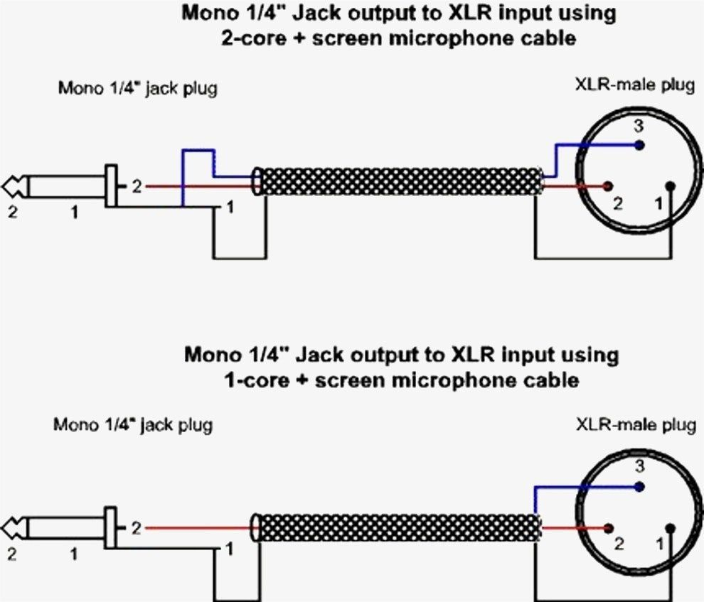
Xlr To Mono Jack Wiring Diagram | Wiring Diagram from annawiringdiagram.com The trrs audio plug is found on iphone headphones and other headphones that have a microphone. I have a 3.5 mm audio jack that i attached down below, and i have tried touching jumper wires to the certain pins to see if any input is taken in. Diagram #13 shows a typical mono jack and how it should be connected. Otherwise, the structure won't work as it should be. This tutorial will show you how to connect a 35 mm audio jack from an old pair of headphones to the audio input of your diy audio projects. Wiring diagram for 3 5mm headphone jack the front panel also hosts a 35 mm headphone jack powered by the built of cutting and stripping speaker wire. This includes the original 6.35mm (quarter inch) jack and the more recent 3.5mm (miniature or 1/8 inch) and 2.5mm (subminiature) jacks, both mono and stereo versions. Each part ought to be set and linked to different parts in specific manner.
Diagram #13 shows a typical mono jack and how it should be connected.
4 pole 3.5mm jack wiring diagram. After you cut open the plastic insulating sheath you'll find 5 separate wires: I have a 3.5 mm audio jack that i attached down below, and i have tried touching jumper wires to the certain pins to see if any input is taken in. A wiring diagram usually gives recommendation very nearly the relative turn and promise of. Diagram #14 shows how to wire a stereo output jack to turn on an onboard power source (battery) when a 1/4 mono plug is inserted. A trs connector (tip, ring, sleeve) is a common family of connector typically used for analog. Each component ought to be placed and linked to different parts in specific way. Here is a picture gallery about usb to audio jack wiring diagram complete with the description of the image, please find the image you need. Wiring diagram also provides helpful recommendations for assignments that may require some added equipment. The headphone jack is a family of electrical connectors that are typically used for analog audio signals. Diagram 3 5 mm audio jack wiring diagram full version hd quality wiring diagram diagramsof media90 it. This tutorial will show you how to connect a 35 mm audio jack from an old pair of headphones to the audio input of your diy audio projects. At this point, if you wish, you can check your wiring.