Wiring diagram, howtos and diy wiki blog with HD images
Home
› 2 Speed Cooling Fan Wiring Diagram - Ls Swap Dual Fan Wiring The 1947 Present Chevrolet Gmc Truck Message Board Network : Now break out your meter and wiring diagram that's in the back of the haynes/chilton manuals.
2 Speed Cooling Fan Wiring Diagram - Ls Swap Dual Fan Wiring The 1947 Present Chevrolet Gmc Truck Message Board Network : Now break out your meter and wiring diagram that's in the back of the haynes/chilton manuals.
2 Speed Cooling Fan Wiring Diagram - Ls Swap Dual Fan Wiring The 1947 Present Chevrolet Gmc Truck Message Board Network : Now break out your meter and wiring diagram that's in the back of the haynes/chilton manuals.. For this set up we also used two of the speedway universal electric radiator cooling fan, part number 910158, which comes in a 10, 12, 14, or 16 inch diameter. Diagram 12 volt relay with toggle switch wiring diagrams full version hd quality ginnering pole prepa sat fr. Now break out your meter and wiring diagram that's in the back of the haynes/chilton manuals. Automatic 2 speed fan control ok here is a true 2 speed fan control. This wiring diagram uses three relays.
With dual cooling fans, there are two methods for wiring up the relay kit. The fans run in series. Lets say we put both fans in series. First ck voltage readings at the fan connector for low and hi speeds. Don't try to pwr both hi and lo at the same time.
Silveradosierra Com Electric Cooling Fans Not Working Vortec 4800 4 8l V8 from www.silveradosierra.com Make a jumper wire so you can test the fan directly from the battery. Reference diagrams #7&8onpage 2 the electric fan assembly is built using a high output two speed motor. It has to run through a relay here is a guide to help you test the relay with the fan wiring diagrams below. Reverse the blade or wiring. Don't try to pwr both hi and lo at the same time. Fan speed control the idea here is that fans are 12 volt motors, and typically will work at reduced capacity at a lower voltage. Hi paul, i have the wiring diagram image for you. Each should have the capacity of a single fan.
The pcm is responsible for controlling both a/c operation and electric fan operation.
The cooling fan wiring diagram below is what we've found to be the simplest and most reliable method. The fan is a 2 speed fan, the black is ground. For this set up we also used two of the speedway universal electric radiator cooling fan, part number 910158, which comes in a 10, 12, 14, or 16 inch diameter. Mount the fan as high up on the core as possible. For a couple seconds, then swap the test lead to the orange stripe wire, you can definately tell which one is high speed. The two speed cooling fan system uses three relays to control the cooling fan operation. By admin | december 4, 2017. Dual radiator cooling fans wiring process The ls1 camaro and firebird are fitted with two electric fans and manual a/c controls. 3 pin and 4 fan wire diagrams cooler master faq pc question about sd controllers silverstone sst fm182 2 vs ft05 caseods linus tech tips how fans work cooling monitor circuit fridge what is pwm does it ekwb com tricks codrey electronics solved cpu failure optiplex 755. Don't try to pwr both hi and lo at the same time. The vcrm will then increase fan speed gradually. The fan pulls way too much current for that.
The pcm is responsible for controlling both a/c operation and electric fan operation. You can always check by using test leads and a battery, black the ground post, blue to pos. When installing electric cooling fans, it is important to cover as much surface area as possible. 12 volt computer fan wiring diagram. Check out the diagrams (below).
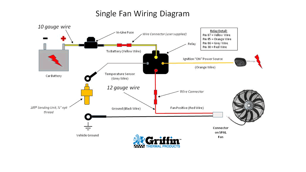
Single Fan Wiring Diagram from www.griffinrad.com Each part ought to be set and connected with different parts in particular manner. This wiring diagram uses three relays. Compatible with all hayden fan controllers. Don't try to pwr both hi and lo at the same time. 3ø wiring diagrams 1ø wiring diagrams (form a) m 3~ m 3~ high speed delta ( ) connection low speed star ( ) connection w2 or white w2 or white u2 or black u2 or black v2 or orange v2 or orange u1 or red u1 or red v1 or yellow v1 or yellow w1 or blue w1 or blue thermal contacts (tb) white thermal contacts (tb) white l1 l1 l2 l2 l3 l3 e e codes. The vcrm will then increase fan speed gradually. Both fans are run in parallel. The fans run in series.
You can always check by using test leads and a battery, black the ground post, blue to pos.
3ø wiring diagrams 1ø wiring diagrams (form a) m 3~ m 3~ high speed delta ( ) connection low speed star ( ) connection w2 or white w2 or white u2 or black u2 or black v2 or orange v2 or orange u1 or red u1 or red v1 or yellow v1 or yellow w1 or blue w1 or blue thermal contacts (tb) white thermal contacts (tb) white l1 l1 l2 l2 l3 l3 e e codes. Than use a 30 am. 2 speed electric cooling fan wiring diagram youtube ford blower motor resistor wiring diagram 0daf light source wiring diagram wiring resources 2005 ford f150 wiring harness automotive wiring schematic 4 pin 7 pin needs and uses ford f150 forum community of ford wiring diagram for 1983 ford f150 wiring diagram t1. It has to run through a relay here is a guide to help you test the relay with the fan wiring diagrams below. The gray wire is high speed and the black wire is ground, but do not just go trying to hook it up to a toggle switch or something like that. Fan wiring harness with relay and fuse holder fan thermostat, 185 degrees / 195 degrees installing the fan: This is based on the draw from the fans, if the fans are larger and draw more than 15 amps each, it's recommended to install a second relay kit as shown below. Testing low and high speed cooling fan relays. Start your wiring project by taking both of the positive wires from the fans and run them to the yellow wires on each relay (tab 87). Hi paul, i have the wiring diagram image for you. When the a/c controls are turned on, the pcm receives a 12v on signal, and validates a/c operation through a pressure sensor and 12v a/c compressor clutch status circuit. Don't try to pwr both hi and lo at the same time. Fan speed control the idea here is that fans are 12 volt motors, and typically will work at reduced capacity at a lower voltage.
When the a/c clutch is engaged, the fan runs on low, until pressure increases above 150 psi in the a/c high side; The pcm is responsible for controlling both a/c operation and electric fan operation. I am almost certain that the one with the orange stripe is high, and the blue is low. With dual cooling fans, there are two methods for wiring up the relay kit. Reverse the blade or wiring.
Dual Cooling Fan Wiring Diagram Electric Cooling Fan Radiator Fan Electric Cooling from i.pinimg.com The fan pulls way too much current for that. For this set up we also used two of the speedway universal electric radiator cooling fan, part number 910158, which comes in a 10, 12, 14, or 16 inch diameter. The vcrm will then increase fan speed gradually. The gray wire is high speed and the black wire is ground, but do not just go trying to hook it up to a toggle switch or something like that. 12 volt computer fan wiring diagram. Attach the fan to the small area around the Just an idea on how to wire up electric cooling fans for your vehiclecooling fans: The two speed cooling fan system uses three relays to control the cooling fan operation.
Mount the fan as high up on the core as possible.
Start your wiring project by taking both of the positive wires from the fans and run them to the yellow wires on each relay (tab 87). 3ø wiring diagrams 1ø wiring diagrams (form a) m 3~ m 3~ high speed delta ( ) connection low speed star ( ) connection w2 or white w2 or white u2 or black u2 or black v2 or orange v2 or orange u1 or red u1 or red v1 or yellow v1 or yellow w1 or blue w1 or blue thermal contacts (tb) white thermal contacts (tb) white l1 l1 l2 l2 l3 l3 e e codes. The correct way to wire an electric fan. Check out the diagrams (below). The fans run in series. Diagram wiring of 240sx ignition 94 full version hd quality cdeblackfriday trodat printy 4923 fr. 2 speed electric cooling fan wiring diagram youtube ford blower motor resistor wiring diagram 0daf light source wiring diagram wiring resources 2005 ford f150 wiring harness automotive wiring schematic 4 pin 7 pin needs and uses ford f150 forum community of ford wiring diagram for 1983 ford f150 wiring diagram t1. Make a jumper wire so you can test the fan directly from the battery. I am almost certain that the one with the orange stripe is high, and the blue is low. Each part ought to be set and connected with different parts in particular manner. Mount the fan as high up on the core as possible. If you choose to operate the fan using both speeds, two switching devices or a derale dual fan controller part # 16788 or 16789 is recommended. For a couple seconds, then swap the test lead to the orange stripe wire, you can definately tell which one is high speed.